When working in Visual Designer, a lot of the complexity of driving the turtle is provided by several high level methods that abstracts much of the electronics complexity, leaving the user to focus on the control algorithms. Since each turtle is made up of different pieces the driver methods in Visual Designer for each are also different. These are discussed below.
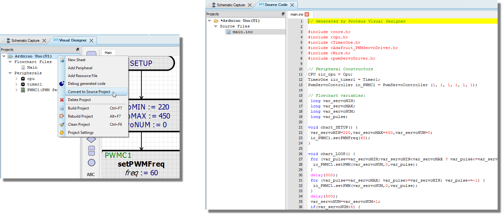
Advanced users can simply convert their project to a source code project via the context menu command on the project tree and then write their programs in Arduino C.
Once a program is switched to be a source code project from a flowchart project you cannot switch back.
This may have some advantages as users can access the on board peripherals (e.g. gyro, accelerometer) at the register level but will undoubtedly be more challenging. At the end of the day, the Proteus simulation is of the real hardware however which means that users can develop their programs in whatever way they want. In particular, it means that 3rd party libraries and source code examples on the internet can be added, used and tested in a Proteus code project.
Control of the turtle falls into three categories :
There are three sensors underneath the Funduino turtle. These provide a digital response to the circuit based on whether they detect the line or not. In Visual Designer we query these sensors with a single decision block called the sensor function. You use the sensor function by dragging and dropping directly from the peripheral in the project tree as shown below:
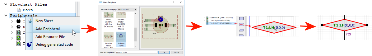
We then need to edit the decision to test the sensors based on a set of conditions we wish to be true. There are three parameters corresponding to the left, center and right sensors and for each one we can test as follows:
1 : Must be TRUE.
0 : Must be FALSE.
-1 : Don't care.
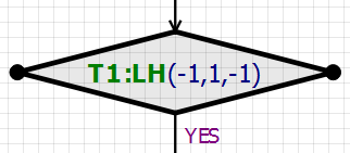
If we want to test that all 3 sensors are over the line we would set all three parameters to 1.
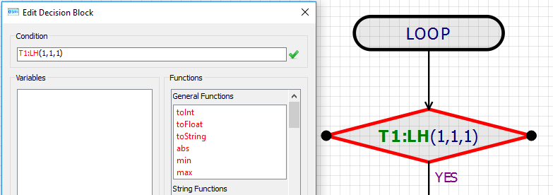
All three sensors can see the line
When this decision is true you know that the turtle is fully over the line and you may choose to attempt some damping or correction if the turtle is wobbling.
If we want to check when we need to make a sharp turn right then we are looking at the case when only the right hand sensor is picking up the line.
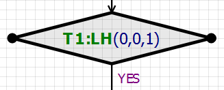
Only the right hand sensor sees the line
If we want to simply drive forwards then testing that the middle sensor is over the line is likely sufficient, provided we do so after other relevant conditions have been tested.
The ultrasonic sonar sends out short bursts (pings) to detect obstacles and is mounted on a rotatable unit. This allows users to first position the sonar head and then check for obstacles inside a certain range. There are three methods and a sensor function for the sonar head.
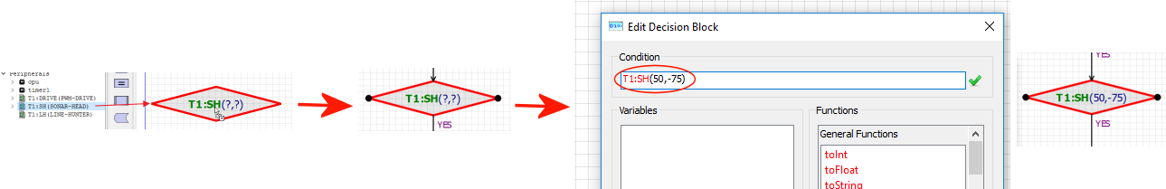
The sensor function is a decision block that allows you to query the peripheral and it is used by dragging and dropping from the peripheral itself in the Project Tree. In the case of the Sonar Head the decision block takes two arguments for distance and head angle. It returns true if an object is detected within the specified distance at the given head angle. The example below would return TRUE if an obstacle was within 50cm on the left of the turtle.
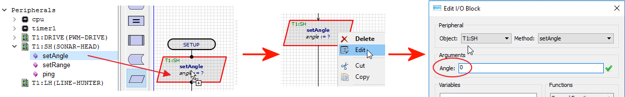
The setAngle() method allows you to position the sonar head. For most applications this will be added to the setup routine with a value of 0 (start by looking straight ahead) and then if required through program execution.
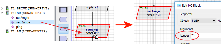
The setRange() method allows you to specify the maximum range in which you want to detect obstacles. This is significant as it determines the time-frame in which the firmware will consider the reply to a ping to count as a reflection from an obstacle. You would normally set this (as small as possible) inside the setup routine and then adjust as required in the program.
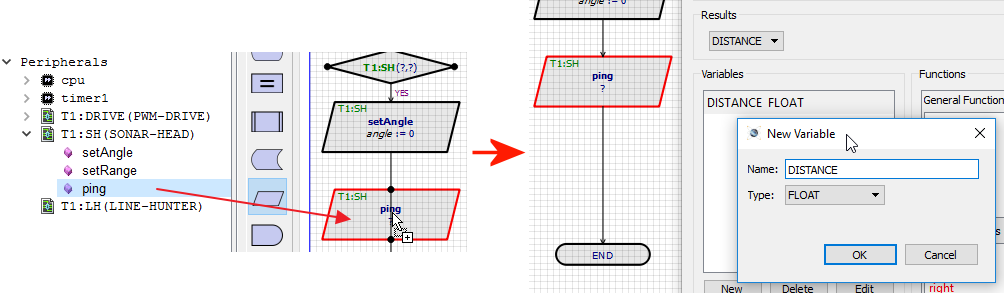
The ping() method fires a sonar burst, converts time to response into distance in cm and returns either that value or -1 if nothing is detected. After placement, the user must edit the method call and assign the return value to a variable.
This variable must be a FLOAT variable otherwise it will not appear in the 'Results' drop down list.
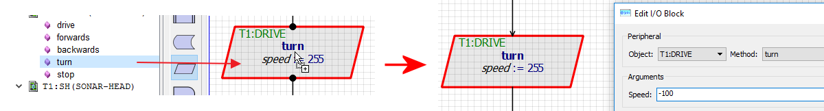
The Drive methods give control over the left and right wheels of the motor. The user is presented with a series of simple control methods as follows.
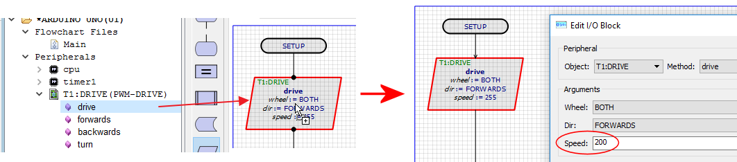
The drive method allows you to specify the wheel(s) to control, the direction of travel and the speed. The latter is a value from 0 -> 255 and represents the duty cycle of the PWM drive signal. For example, you might set up full speed ahead as both wheels forwards at around speed 200.
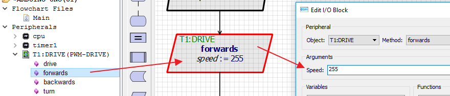
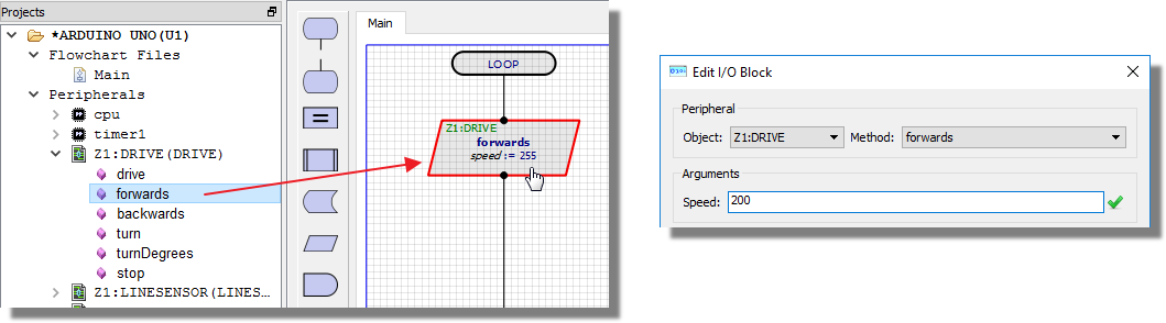
With the forwards() method the direction of travel is explicit and so all that is needed is the speed value.
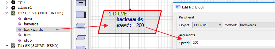
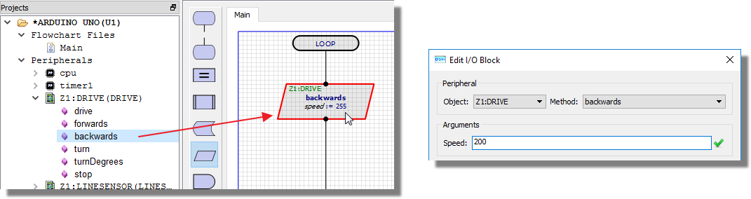
As with the forwards() method, all that is needed is the speed at which to reverse.
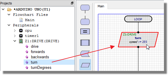
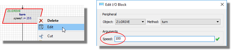
The turn() method simplifies the turning of the turtle by allowing you to specify a speed of turn. Negative values turn left while positive values turn right and the magnitude of the value is the speed of turn. In practise, this will execute a turn by turning one wheel forwards and the other backwards at the specified speed. It can therefore be thought of as a sharp turn where a soft turn involves stopping one wheel and turning the other.
The same effect can be achieved with greater precision by using the drive() command twice and controlling speed of wheels independently.
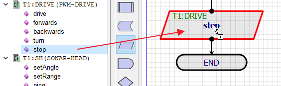
The stop() method immediately stops drive of both wheels.
Control of the Zumo turtle in Visual Designer falls into three basic categories :
The Zumo comes with a mounted array of six IR reflectance sensors that allows the Zumo to detect contrasts in reflectivity directly beneath its blade, which can be used for following lines or detecting edges. Each reflectance sensor consists of an IR emitter coupled with a phototransistor that responds based on how much emitter light is reflected back to it. Unlike the Funduino therefore, the Zumo is well suited to Proportional Integral Derivative (PID) control algorithms when line following.
- Takes no parameters
- Returns an integer between 0 and 6000 indicating the position of the line underneath the six IR sensors.
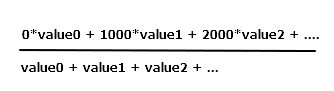
This method first reads the calibrated value from each of the six sensors into an array. Values per sensor range from 0 to 1000 where and are a measure of the reflectance in abstract units, with higher values corresponding to lower reflectance (e.g. a black surface or a void). An estimated position of the robot with respect to the line is then calculated used a weighted average of the sensor values multiplied by 1000. This means that a return value of 0 means that the line is directly under sensor 0, a return value of 1000 indicates that the line is directly below sensor 1 and so on. Intermediate values indicate that the line is between two sensors. The formula used is :
Example:
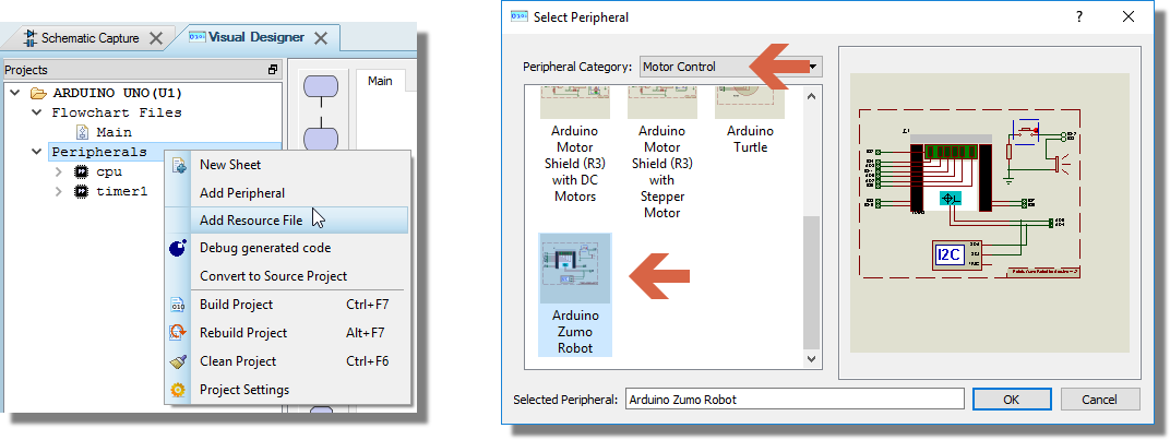
1) Add the Zumo turtle to the Visual Designer Project.
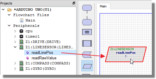
2) Drag and drop the readLinePos() method onto the flowchart.
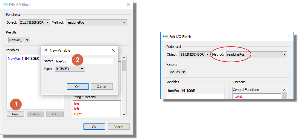
3) Edit the method and create an integer variable (e.g. linePos). Set the variable to store the return value from the method.
If you get a value of 0 the line is underneath the far left hand sensor, 1000 means the line is flush underneath the second sensor from the left, 2500 means that the line is right in the middle of the turtle between sensors 3 and 4 and a value of 6000 means that the line is underneath the far right sensor.
- Takes an integer parameter corresponding to the index of the IR sensor you want to read (0..5).
- Returns the raw (uncalibrated) value from the specified sensor.
The number returned is based on the reflectance. The higher the number, the less reflectance so a black line gives a high value. The numbers are not calibrated meaning that care is required with return values as they would change under different conditions in the real world.
Example:
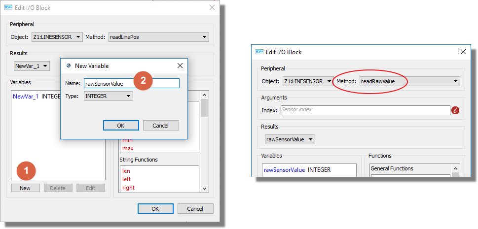
1) Drag and drop the readRawValue() method onto the flowchart.
2) Edit the method and create an integer variable (e.g. rawSensorValue). Set the variable to store the return value from the method..
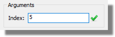
3) Set the index parameter to specify which sensor you want to query. 0 is the left hand sensor, 5 is the right hand sensor.
The Zumo includes an integrated LSM303D chip which can be controlled by the following Visual Designer methods:
- Takes three floating point parameters (void readMagneticField (float *magX, float *magY, float *magZ))
- Returns the X,Y,Z components of the magnetic field in units of Gauss.
This method passes in pointers to three floating point variables and the internal routine then populates them with the X,Y and Z components of the magnetic field. Note that the compass is widely inaccurate in relative and absolute terms. I.e. the vector is offset from the origin and North is impossible to determine without calibration.
In the read device the compass gets a lot of interference from the motors, batteries, PCB, and its surroundings, so it is not generally useful for precision navigation. However, having been calibrated it can be used for rough orientation measuring in many environments.
Example:
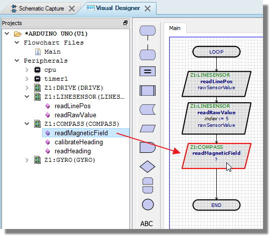
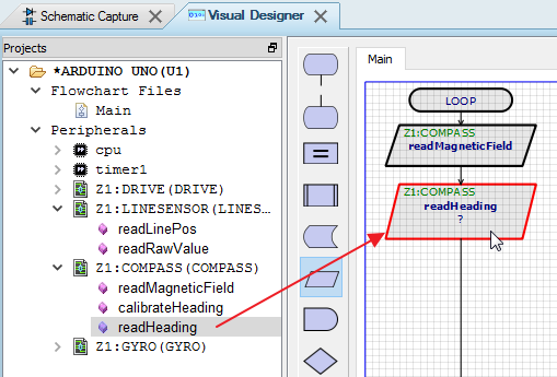
1) Drag and drop the method onto the flowchart.
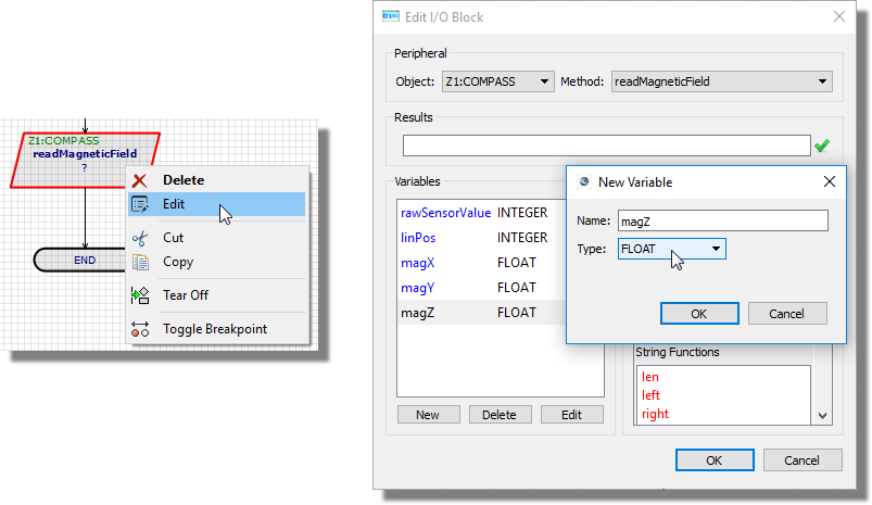
2) Edit the method and create three new variables (e.g. magX, magY, magZ)
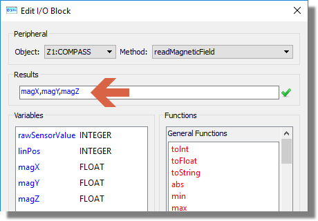
3) Enter the three variables in to the Results field separated by a comma. This passes the three variables as parameters to the method.
- Takes no parameters
- Returns no values
This function uses the drive method to spin the Zumo on the spot and take multiple magnetic readings. It takes the minimum and maximum X and Y magnetic values found and uses these to calculate the centre. It stops spinning when no new min or max values are set over a period of 500ms. Before calling this function it assumes the Zumo is facing North. Thus is uses the first magnetic reading to work out the angle of the vector that points to North.
- Takes no parameters
- Returns a float representing the heading.
This function requires calibrateHeading() to have been called. If it hasn't then -1.0 is returned. Otherwise the heading angle in degrees limited to [-180.0, +180.0] is returned (0 is North).
Example:
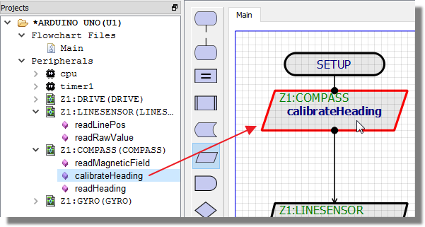
1) Drag and drop the calibrateHeading() method onto the flowchart. This is best done at the very beginning where the Zumo can be pointed north so the setup routine makes sense.
2) Drag and drop the readHeading() method anywhere after the calibration routine.
3) Edit the readHeading() method and create a variable of type float (e.g. heading) to receive the function return.
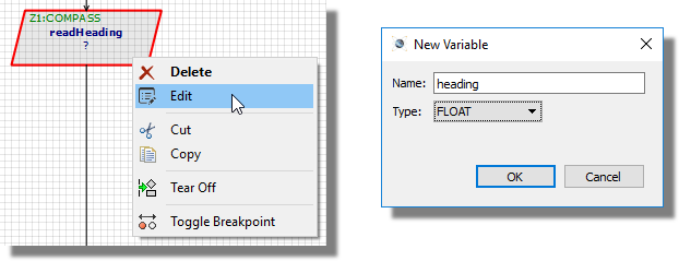
A value of 0 means the Zumo is pointing north, a value of 180 means South, a value of -90 means West and so on.
The Zumo (V1.2) includes an integrated L3GD20H 3-axis gyroscope that can be used to track rotation and, together with the LSM303D effectively provides an inertial measurement unit that programs can use. The Visual Designer wraps some of this functionality in two high level methods:
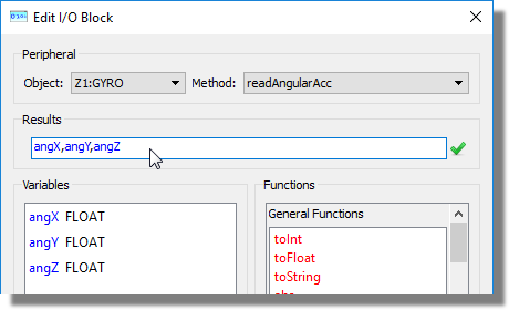
- Takes three floating point parameters (void readAngularAcc(float *angX, float *angY, float *angZ))
- Returns the X,Y,Z components angular acceleration in units of degrees per second.
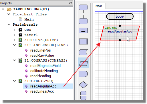
This function returns the angular acceleration of the Zumo in three dimensions. Note however, that due to the 2D nature of the simulation environment, only the angZ parameter will be non-zero.
Example:
1) Drag and drop the method onto the flowchart.
2) Edit the method and create three new variables (e.g. angX, angY, angZ)
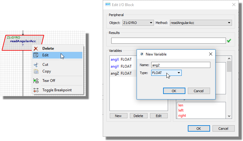
3) Enter the three variables in to the Results field separated by a comma. This actually passes pointers to the three variables into the method which will then return the relevant values.
- Takes three floating point parameters (void readLinearAcc (float *linX, float *linY, float *linZ))
- Returns the X,Y,Z components angular acceleration in units of G.
This function returns the linear acceleration in three dimensions.
The actual measurement of linear acceleration is on the LSM303 device
whereas the angular acceleration is read from the L3GD20H device. Linear
acceleration is a tricky one to measure in a simulation environment as
it happens over such a short amount of time. The following is an explanation
of the implementation:
The physics modelling does not simulate acceleration - when a the turtle
is driven it sets the speed instantaneously. The reason for this is that
the turtle and Zumo get up to speed so quickly there was any point in
modelling it. However, this is no good if you're measuring linear acceleration.
So acceleration has been modelled by looking at the change in velocity
from one (simulation) frame to the next and limiting the change to a maximum
of 1G for driven acceleration and 10G for collisions. Obviously, 1G accelerations
occur over more frames than 10G accelerations and therefore are more successful
to catch when polling the device for changes.
In practice, we assume the linear acceleration may be used in a tight loop to test against a collision with an obstacle. We welcome feedback on this - tell us what you are doing and if our implementation is lacking.
The Zumo contains two integrated micro metal gearmotors with a DRV8835 dual motor driver to control them. The following methods are used in Visual Designer to control this hardware.
- Takes three parameters (which wheel, which direction and what speed).
- Has no return value.
This is the workhorse method to move the Zumo turtle. It allows you to drive one or both of the wheels in a direction and speed of your choice.
Example:
1) Drag and drop the drive method onto the flowchart
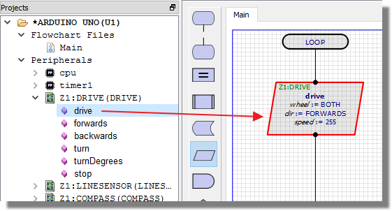
2) Edit the method and specify the wheel and direction to drive.
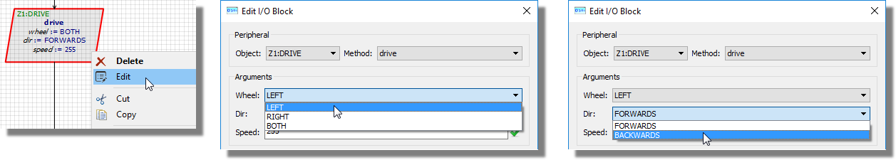
3) Specify the speed at which you want to drive the wheel. This is a value between 0 and 255 where 255 represents full speed.
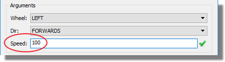
The range 0..255 are used because they represent a byte and at a lower level the motor is driven electronically by altering the duty cycle of a PWM signal (using the Arduino analogWrite() method).
- Takes one parameter for speed.
- Has no return value.
With the forwards() method the direction of travel is explicit and so all that is needed is the speed value.
- Takes one parameter for speed.
- Has no return value.
As with the forwards method except driving the turtle straight backwards at the specified speed.
- Takes one parameter for speed.
- Has no return value.
The turn command allows the Zumo to turn either clockwise or anti-clockwise at a given speed. The range of the speed parameter is -255..255 where :
-255 -> 0 : turn anti-clockwise by driving right wheel forwards and left wheel backwards.
0->255 : turn clockwise by driving left wheel forwards and right wheel backwards.
Example:
1) Drag and drop the method onto the flowchart.
2) Edit the method and set the speed value between 0 and 255. Prefix with a minus sign if you want to turn anti-clockwise.
- Takes two integer parameters, one for the number of degrees to turn and the second for the speed of turn.
- Has no return value.
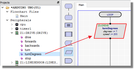
The turnDegrees() method allows you to control the amount of turn programmatically. You specify the number of degrees that you want to rotate (0..360) and the speed at which you wish to do so (-255...255).
Internally, this method uses the gyro, reads the angular acceleration in Z and then calculates the time needed to turn the specified number of degrees. It follows that, while fairly accurate, it will be an approximation.
Example:
1) Drag and drop the method onto the flowchart.
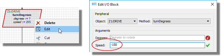
2) Edit the method and set the speed value between 0 and 255. Prefix with a minus sign if you want to turn anti-clockwise.
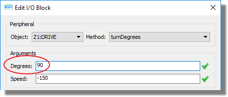
3) Set the number of degrees to turn.
- Takes no parameters
- Has no return value
This method will stop the motor drive and bring the turtle to a halt.